

How To Set Drawing Limits In Autocad 2015
Limits Command
The Limits command in AutoCAD is used to ready an invisible rectangular purlieus in the drawing area or viewport. It limits the grid display and the point locations.
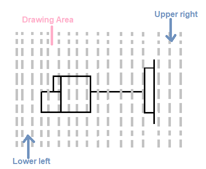
We are required to specify the coordinates of the opposite corners of the rectangular window. The opposite corners are named as Upper right and Lower left corners.
The opposite corners are shown in the below epitome:
Why we demand limits?
Some dimensions in a drawing are represented in hundreds and thousands of meters. For example, span designing in AutoCAD, Architecture designing, etc.
The representation of such large dimensions is difficult in a regular drawing expanse. For such purposes, limits play a vital office in setting the boundary of the drawing expanse. We tin specify the limits according to our requirements.
Limits Checking
The two options under limits checking are:
- ON
It turns ON the limit checking. It tests merely the points we enter, so nosotros cannot specify the points outside the filigree limits. But portions of circles and other objects can extend outside the grid limits. - OFF
Information technology turns OFF the limit checking. The current value of limits is maintained for the next time when we turn ON the limits.
Steps to set the limits
The steps to prepare the limits are listed beneath:
- Open up the AutoCAD software.
- Type LIMITS on the command line or command prompt.
- Press Enter or spacebar.
- Write the coordinates of the lower-left corner. For example, (0,0). The coordinates for the lower-left are commonly the coordinates of origin for meliorate understanding. Nosotros can also modify the coordinates according to the requirements.
- Printing Enter.
- Write the coordinates of the upper-right corner. For example, (200, 200).
- Press Enter.
- Write Z. Hither Z signifies Zoom.
- Press Enter.
- Write E. Here, East signifies Extend.
- Press Enter.
The Z and East are mandatory to activate the limits. Information technology is also called a regenerating way of limits.
Now, nosotros can quickly create drawings inside the dimensions mentioned above.
Annotation: The dimensions of a effigy should exist within the specified limits. If it is greater, we can re-specify the limits according to the requirements.
Permit's empathise limits with few examples.
Case 1:
Draw a rectangle of dimension 100 x 200.
Here, the length of the rectangle is 100, and the width is 200.
The steps are listed below:
- Type LIMITS on the command line or command prompt.
- Press Enter.
- Write the coordinates of the lower-left corner (0, 0).
- Press Enter.
- Write the coordinates of the upper-right corner (300, 400). You can also increase the limits according to your selection.
- Press Enter.
- Write Z. Here Z signifies Zoom.
- Printing Enter.
- Write E. Here, Eastward signifies Extend.
- Printing Enter.
- Blazon Rec or Rectangle on the command line.
- Press Enter.
- Specify the starting time corner point on the viewport.
- Specify the length and breadth of the rectangle in the form of @length, width. For example, @100,200
- Press Enter.
Using higher up steps, the rectangle volition be created.
Example ii:
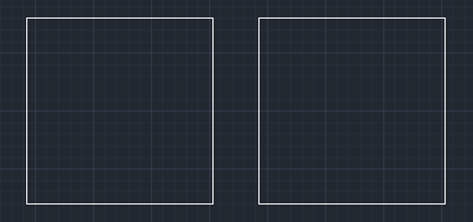
Describe 2 adjacent squares of side 200. The gap betwixt the squares should be 50.
The length of the figure volition be 200 (side of square1) + 50 (gap) +200 (side of square2) = 450. So, nosotros will specify the limits greater than the dimensions of the figure.
The steps are listed below:
- Type LIMITS on the command line or command prompt.
- Press Enter.
- Write the coordinates of the lower-left corner (0, 0). You can set the coordinates according to the pick.
- Press Enter.
- Write the coordinates of the upper-right corner (700, 600). You lot can also increase or adjust the limits according to your option.
- Press Enter.
- Write Z. Hither Z signifies Zoom.
- Press Enter.
- Write Eastward. Here, Eastward signifies Extend.
- Printing Enter.
- Type Rec or Rectangle on the command line.
- Press Enter.
- Specify the beginning corner betoken on the viewport.
- Specify the length and breadth of the rectangle in the course of @length, width. For case, @200,200
- Printing Enter.
Now, we will draw another square side by side to the first square. For the gap of 50, we volition move the 2d foursquare and will specify the displacement value 50. Y'all can apply other methods as well. - Again type Rec or Rectangle on the control line.
- Press Enter.
- Specify the corner point of the first square.
- Specify the length and breadth-@200,200
- Printing Enter.
- Blazon M or Move on the command line and press Enter.
- Select the second square.
- Press Enter.
- Specify the base of operations signal and requite the management through the cursor.
- Write the deportation = 50.
- Press Enter.
The figure will be created, as shown in the below image:

How To Set Drawing Limits In Autocad 2015,
Source: https://www.javatpoint.com/autocad-limits-command
Posted by: marquezsuble1955.blogspot.com
0 Response to "How To Set Drawing Limits In Autocad 2015"
Post a Comment